Analysis Sell · interconnection
Meet-Me Room (MMR) in a Data Center: How It Works
What a meet-me room does, what the standards say, and a worked loss budget showing when a cross-connect path through it stops working.
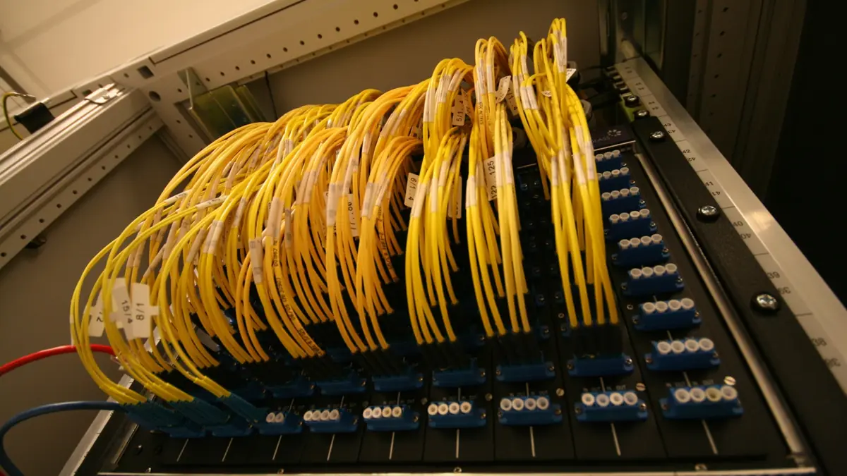
A meet-me room (MMR) is the space in a colocation building or carrier hotel where networks physically connect to each other. Carriers bring their fibre into the room, customers run cabling to it from their cages, and a cross-connect (a patched fibre pair between two panels) joins them. The room decides which networks a tenant can reach, how quickly a new circuit can be delivered and whether a link will work at all once every patch panel on the path is counted.
Key takeaways
- The meet-me room is the demarcation and cross-connect space where carrier networks meet customer cabling; in TIA-942 terms it performs the role of the entrance room.
- Large European interconnection sites list hundreds of networks in PeeringDB, for example 617 at Digital Realty FRA1-27 in Frankfurt and 495 at Telehouse North in London.
- Distance inside the building costs microseconds, not milliseconds: a 300 m cross-connect adds about 1.5 µs of propagation delay.
- Connectors cost more than distance. At the TIA maximum of 0.75 dB per mated pair, a four-panel path of 300 m single-mode reaches 3.3 dB and exceeds the roughly 3.0 dB allowed for a short-reach DR optic in Fluke Networks’ example.
The Structure of the Meet-Me-Room: More than Just Space
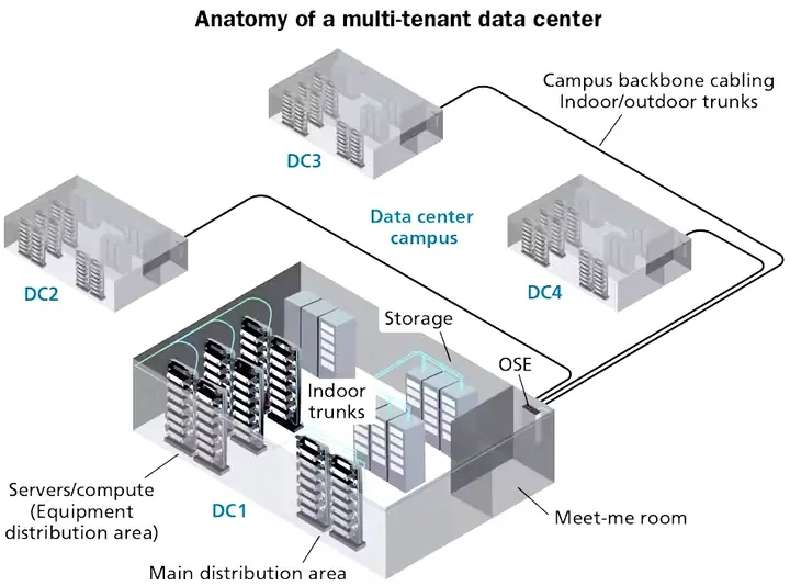
Inside the room are two kinds of racks. Optical distribution frames (ODFs) hold the passive patch panels where cross-connects are made. Carrier racks hold the equipment that terminates each carrier’s external cables. Fibre arrives from the street through diverse building entrances, lands on the carrier side, and is patched across to panels that lead to customer cages elsewhere in the building.
Standards describe the same function under other names. Fluke Networks’ summary of TIA-942 defines the entrance room as the place where service enters the data centre, “providing the demarcation point to service provider networks”, and the main distribution area as the central point of distribution. The current revision, ANSI/TIA-942-C, was published on 9 May 2024. In Europe, EN 50600-2-4:2023 covers telecommunications cabling, including pathways, spaces and enclosures, and points to EN 50173 for design and EN 50174 for installation and quality assurance. Both standards are sold rather than published free, so their detailed requirements are not quoted here.
The size of an MMR follows the number of carriers and tenants it has to serve, not a Tier label. The Uptime Institute’s Tier Standard is outcome based and does not prescribe designs, and Uptime removed expected downtime figures from its Tier definitions in 2009. Tier IV means fault tolerance, not a fixed uptime percentage. A building that must survive a fire or cable cut in one room can split carriers across two separate MMRs fed by diverse entrances.
Carrier Diversity and Redundancy: Ensuring Business Continuity
The MMR’s commercial value is choice. In a carrier-neutral building, the operator runs the room and any carrier can enter it. In a carrier-owned building, the room belongs to one network, which may shape who else is admitted. Neutral hubs gather large ecosystems. Networks’ own declarations in PeeringDB, queried on 22 September 2026, show:
| Facility | City | Networks listed | Exchanges listed |
|---|---|---|---|
| Digital Realty FRA1-27 | Frankfurt | 617 | 31 |
| Equinix FR5 | Frankfurt | 553 | 37 |
| Telehouse London Docklands North | London | 495 | 14 |
| Telehouse Paris 2 Voltaire | Paris | 358 | 17 |
| CoreSite LA1, One Wilshire | Los Angeles | 334 | 5 |
| Equinix AM7 | Amsterdam | 217 | 13 |
Diversity protects a customer only if the customer uses it. The MMR does not reroute traffic by itself. Surviving a carrier outage requires circuits from at least two carriers, ideally over physically separate entrances and routes, plus routing (usually BGP) that fails over between them. This is one reason networks and latency-sensitive businesses cluster in buildings where many carriers are already present, as the PeeringDB counts above show.
The Impact of Latency on MMR Performance
Light in standard single-mode fibre travels at the speed of light divided by the group index, which Corning gives as 1.4682 at 1550 nm for SMF-28. That works out to about 4.9 µs per kilometre. A 300 m path from a cage to the MMR and on to a carrier panel therefore adds about 1.5 µs, and a 2 km campus link about 10 µs. At the scale of long-haul routes the numbers grow quickly: Equinix announced in 2015 that the Hibernia Express cable connected its New York and London sites with a round trip under 58.95 ms.
For most tenants, the MMR’s contribution to latency is negligible next to the route the carrier takes. It matters to trading firms, and European law treats it seriously. Commission Delegated Regulation (EU) 2017/573 requires trading venues to offer co-location on fair and non-discriminatory terms, including cable length, to publish the fee for each service, and to charge the same fee to all users of the same type of service. Euronext’s colocation price list states that it arranges the same cable length for all clients for this reason.
Worked case: will a cross-connect path through the MMR stay within its loss budget?
The practical design question is not the room’s size but whether a given path will work. Every mated connector pair loses light, and a typical cross-connect passes through four of them: the customer cage panel, the MMR customer-side ODF, the MMR carrier-side ODF and the carrier’s panel. The case below adds up worst-case loss using the design maxima from TIA-568, as tabulated by the Fiber Optic Association and Fluke Networks: 0.75 dB per mated pair, 0.3 dB per splice, 1.0 dB/km for single-mode premises cable, 0.5 dB/km for outside plant and 3.0 dB/km for OM4 at 850 nm. The optic budgets come from Fluke Networks’ 2025 guide: about 3.0 dB for a 400GBASE-DR4 channel with four connectors, 6.3 dB for 10 km LR optics and 1.8 dB for 400GBASE-SR4 over 100 m of OM4.
| Path | Mated pairs | Worst-case loss | Optic budget | Result |
|---|---|---|---|---|
| Single-mode premises cable, 300 m | 4 | 0.3 + 3.0 = 3.3 dB | DR, about 3.0 dB | Over by 0.3 dB |
| Single-mode premises cable, 300 m | 2 | 0.3 + 1.5 = 1.8 dB | DR, about 3.0 dB | Fits, 1.2 dB margin |
| Single-mode premises cable, 300 m, 2 splices | 4 | 0.3 + 3.0 + 0.6 = 3.9 dB | LR, 6.3 dB | Fits, 2.4 dB margin |
| OM4 multimode, 100 m | 4 | 0.3 + 3.0 = 3.3 dB | 400GBASE-SR4, 1.8 dB | Over by 1.5 dB |
| OM4 multimode, 100 m | 2 | 0.3 + 1.5 = 1.8 dB | 400GBASE-SR4, 1.8 dB | Fits, no margin |
| Single-mode outside plant, 10 km, 4 splices | 4 | 5.0 + 3.0 + 1.2 = 9.2 dB | LR, 6.3 dB | Over by 2.9 dB |
The pattern is clear. At worst-case values, a four-panel path fails the short-reach single-mode optics used inside data centres, even over a few hundred metres, because the connectors take most of the budget. The same path is comfortable for a 10 km LR optic until the fibre itself is long. Three responses follow: order low-loss connectors and ask for their certified loss values, remove intermediate panels where the building layout allows, and test the installed link rather than assume it closes.
Limits of this case: 0.75 dB and 0.3 dB are maximum allowances, and good modern connectors and fusion splices usually lose much less. The IEEE loss limits for DR and FR optics also depend on connector reflectance and the number of reflections, so the 3.0 dB figure is one worked example rather than the full table. Treat the result as a reason to measure, not as a substitute for certification testing of the installed channel.
The Economics of Setting up a Meet-Me-Room
For the building operator, the MMR costs racks, frames, cable pathways, security and the floor space that could otherwise host paying IT load, plus power and cooling for any active carrier equipment. Operators often design the room to be expanded in stages as interconnection demand grows. Cross-connect fees are how that investment is recovered. CoreSite, for example, notes that facilities with dense ecosystems typically command higher rates.
Trading venues are one place where cross-connect prices are public, because the same EU rules require them to publish their co-location fees. ICE’s Basildon colocation price list, effective 12 August 2025, charges £750 installation and £750 a month for a single-mode meet-me-room cross-connect, and bills the telecom provider a further £1,184 per cross-connect. These are premium exchange prices and should not be read as typical colocation rates.
Demand is still growing. Equinix reported a record 9,700 net new interconnections in the second quarter of 2026.
Uptime, SLAs, and the Role of the MMR
Colocation SLAs usually cover what the operator controls: power, cooling and the physical environment. CoreSite, for instance, advertises a 100% uptime SLA at One Wilshire. Latency, jitter and packet loss guarantees belong to the carrier or network service that runs through the room, not to the MMR itself.
The MMR supports those SLAs indirectly. It makes carrier diversity possible, keeps cross-connect paths short and documented, and lets new circuits be patched without entering customer space. When buying a cross-connect, ask who is responsible for each segment of the path, how faults are handed over between the operator and the carrier, and what loss the installed link was tested to.
Fiber Optic Solutions in MMRs: Single-Mode vs. Multi-Mode
Carrier connections into the MMR are single-mode, because single-mode fibre carries signals over kilometres with low loss. Corning specifies a mode-field diameter of 9.2 µm at 1310 nm for SMF-28 and uncabled attenuation of 0.20 to 0.22 dB/km at 1550 nm. Installed cable is rated more conservatively, at the 1.0 and 0.5 dB/km design maxima used in the worked case.
Modern multimode fibre (OM2 to OM5) has a 50 µm core and pairs with cheaper short-reach optics. It is common inside data halls but trades reach for cost. The common 100G multimode optic, 100GBASE-SR4, reaches 70 m on OM3 and 100 m on OM4, in line with the IEEE P802.3bm objective of at least 100 m of multimode fibre. On single-mode, the IEEE P802.3ba objectives set 100G reaches of at least 10 km and 40 km. Those LR4 and ER4 optics run four lanes around 1310 nm, not at 1550 nm.
The Future of Meet-Me-Room Design: 5G and IoT
Growth in connected devices is real but slower than early forecasts. IDC predicted in 2019 that there would be 41.6 billion connected IoT devices in 2025, while IoT Analytics counted 18.5 billion in 2024 and expected about 21.1 billion in 2025. The pressure on MMRs comes less from device counts than from cloud on-ramps, AI clusters exchanging data between sites and edge deployments that push interconnection into more buildings.
Two design consequences follow. Rooms need denser fibre management, because more cross-connects must fit into the same frames. They also need tighter loss budgets, because faster optics tolerate less connector loss, as the worked case shows. Both favour fewer, better connectors on each path over more patch panels.
Conclusion: The Meet-Me-Room’s Role in a Connected Future
The meet-me room is where a building’s connectivity is decided: which networks a tenant can reach, how quickly circuits are delivered and how much loss each path carries. When evaluating a facility, check the carrier ecosystem in PeeringDB, ask for diverse entrances and separate rooms, and count the connector pairs on every cross-connect path before choosing optics. For the wider cabling picture, see our guide to fibre optic infrastructure for data centres.